Logic gates are an important topic if you are studying electronics. These are essential digital devices based mainly on the Boolean function. Logic gates perform logical operations on single or multiple binary inputs and give a binary output. Simply put, logic gates are electronic circuits in a digital system.
For NOR Gate, candidates have to refer the below page info for the truth table, diagram, formula and other important information.
NOR GATE
A NOR gate (“nor gate”) is a logic gate that produces a high output (means 1) if all inputs are false and low output (means 0) otherwise. Hence a NOR gate is the inverse of an OR gate, and its circuit is generated by connecting an OR gate to a NOT gate. Like an OR gate, a NOR gate has any number of input probes but only one output probe.
Here we discussed as a NOT gate followed by an OR gate makes a NOR gate. The basic logic structure of a NOR gate is shown below:
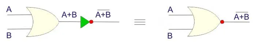
An OR gate is similar to the OR gate, but in the case of the OR gate, a bubble is drawn at the output point of the OR gate.
NOR Gate Truth Table
A NOR gate means “not an OR gate,” so the output of this logic gate is just the reverse of an OR gate.
In working with an OR gate, we know that the output of an OR gate is 0 only when all its inputs are 0. Hence in the case of the NOR gate, the output becomes one only when all inputs are 0. In all other cases, i.e., the output is 0 for all different combinations of inputs.
Like other gates, this is also a simple form of a NOR gate. This type of NOR gate has only two input values and an output value. There are 22=4 combinations of inputs. Truth tables show the output of a particular digital logic circuit for all possible combinations of its inputs. The truth table of an input NOR gate can be represented as follows:
| Input | Input | Output |
| A | B | Y |
| 0 | 0 | 1 |
| 0 | 1 | 0 |
| 1 | 0 | 0 |
| 1 | 1 | 0 |
NOR gate is a universal gate because binary operations can only be realized using NOR gates.
As we know, there are only three basic operations AND, OR, and NOT. Also, we know that all complex binary functions can be realized using these three basic operations.
Here we can prove that AND, OR, and NOT operations can be realized using only NOR gates. We can easily say that binary operations can be realized using NOR gates.
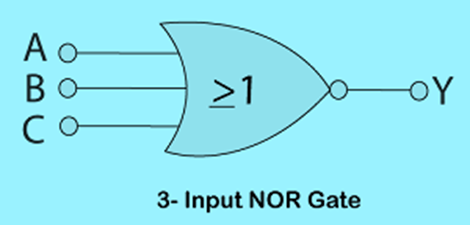
3-input NOR gate
Unlike a 2-input N gate, a 3-input NOR gate has three inputs. The Boolean expression of a logic NOR gate is defined as the binary operation addition (+). A NOR gate can be cascaded together to form individual inputs. There are 23=8 combinations of inputs.
Logic Design
Truth Table
| Input | Input | Output |
| A | B | Y |
| 0 | 0 | 1 |
| 0 | 1 | 0 |
| 1 | 0 | 0 |
| 1 | 1 | 0 |
| 1 | 0 | 0 |
| 1 | 0 | 0 |
| 1 | 1 | 0 |
| 1 | 1 | 0 |
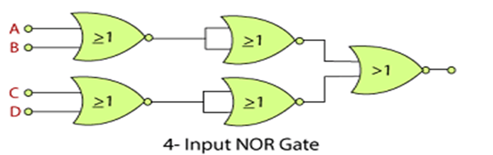
Multi-input NOR Gate
We can also design an n-input NOR gate similar to the NAND gate. If the number of inputs is odd, any “unused” input can be kept low by connecting directly to the power supply using low “matching” pull-up resistors. A 4-input NOR gate has the following expression:
Y=((A+B)+(C+D))’
In simple words, we are explained as:
Y=A NOR B NOR C NOR D.
Logic Design:
Why is the NAND or NOR gate called a universal gate?
- All other gates can be created using these gates. That means the combination of these gates can be used to achieve any function.
- For example, the NOR gate can be used as a NOT gate and an OR gate.
Conclusion:
NOR gate is a Universal gate. All the other gates like AND, OR, and NOT gates can be designed efficiently with a NOR gate. A NOR gate means “not an OR gate,” so the output of this logic gate is just the reverse of an OR gate.
Examdays Article Agenda
