
Logic gates have many applications, but they mainly depend on their operation mode or truth table. Basic logic gates are often found in circuits such as security thermostats, push-button locks, automatic water systems, light-activated burglar alarms, and many other electronic devices. Using Logic gates One of the primary advantages is that basic logic gates can be used in various combinations if the operations are sophisticated.
There is no limit for gates used in a single device. However, this is limited due to the physical space given on the device. In digital integrated circuits (ICs), we find an array of logic gate area units.
AND GATE
The domain of digital electronics logic gates includes devices that perform Boolean operations with two inputs and one output. The logic functionality changes depending on the logic gate, and so does the output. In 1886, Charles Peirce mentioned in a letter how logical operations could be performed by changing circuits.
We are going to discuss and gate today. Walther Bothe invented the first and modern AND gate in 1954. This article describes how to define a gate, its circuit, transistor, multiplexer, and its development using applications.
What is a gate?
AND gate is a digital logic gate with two or more inputs and an output that logically combines. The AND gate output is true only when all inputs are true. If one or more inputs of an AND gate are false, the output of the AND gate is false.
AND Gate Symbol
And gate plays a vital role in a digital logic circuit. The output state of an AND gate is always low when any of the inputs are low. If any input value of an AND gate is set to 0, it will always produce a low output (0). A logic or Boolean expression for an AND gate is a logical multiplication of inputs represented by a single dot.
Example:
A.B=Y
The value Y is actual when both inputs A and B are set to true.
Types of Digital Logic AND Gate:
And the gate is classified into three types based on the input it takes. These are the following types of AND gates:
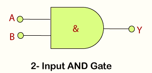
2-input AND Gate
This is a simple structure of AND gate. This type of AND gate has only two input and output values. There are 22=4 combinations of inputs. The truth table and logic design are explained below:
AND Gate circuit diagram
AND GATE Truth Table
| Input | Input | Output |
| A | B | Y |
| 0 | 0 | 0 |
| 0 | 1 | 0 |
| 1 | 0 | 0 |
| 1 | 1 | 1 |
Here is the example in the above table if two values are true, then it will print true otherwise, it will print zero.
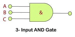
The 3-input AND Gate:
Unlike a 2-input AND gate, a 3-input AND gate have three inputs. The Boolean expression of logic and gate is defined as the binary operation dot(.). An AND gate can be cascaded together to form any number of individual inputs. There are 23=8 combinations of inputs. Here we are explaining the truth table and logic design given below:
Logic Design:
Truth Table:
| Input | Input | Output |
| A | B | Y |
| 0 | 0 | 0 |
| 0 | 1 | 0 |
| 1 | 0 | 0 |
| 1 | 1 | 0 |
| 1 | 0 | 0 |
| 1 | 0 | 0 |
| 1 | 1 | 0 |
| 1 | 1 | 1 |
If three values are true, it will print true(1). otherwise, it will print false(0).
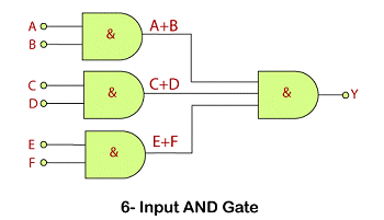
The Multi-input AND Gate:
Truth Table:
Comparison Between AND Gate vs OR Gate:
| Comparison | AND Gate | OR Gate |
| Basic | It performs logical multiplication. | OR gate performs logical summation. |
| Rule | Logical conjunction | Logical disjunction |
| Boolean Expression | X . Y | X + Y |
| Output | A logic high output is achieved when both inputs are necessarily high. | Logic high is achievable in the case of even single high input. |
Examdays Article Agenda
